Speed differential — or draw — around the size press is one of the most consequential yet frequently misunderstood parameters on a paper machine. Set incorrectly in either direction, the consequences range from coating defects and wrinkling to outright web breaks.
This article explains the engineering logic behind draw control, provides practical reference values for size press entry and exit sections, and offers operators a structured framework for setting, calibrating, and adjusting draw across different grades and running conditions.

What Draw Actually Controls
The term ‘speed differential’ is technically accurate but misleading in practice. What draw actually controls is web tension in the open draws between driven sections. Speed is the input; tension is the outcome that matters.
In engineering practice, draw is expressed as a percentage ratio between the linear speed of a downstream section and an upstream section — not as an absolute difference in metres per minute. This distinction matters because roll diameter changes continuously through rubber wear and mechanical tolerance. When diameter changes but RPM is held constant, actual linear speed — and therefore actual draw — shifts without any corresponding change in the control system display. A mill that sets draw in RPM without diameter correction is continuously operating with a hidden deviation between set and actual draw.
Practical check: Express all draw settings as linear speed ratios (%), not RPM. Measure and update roll diameters in the drive control system after every rubber cover change or scheduled maintenance interval.
Typical Draw Distribution: Entry vs Exit
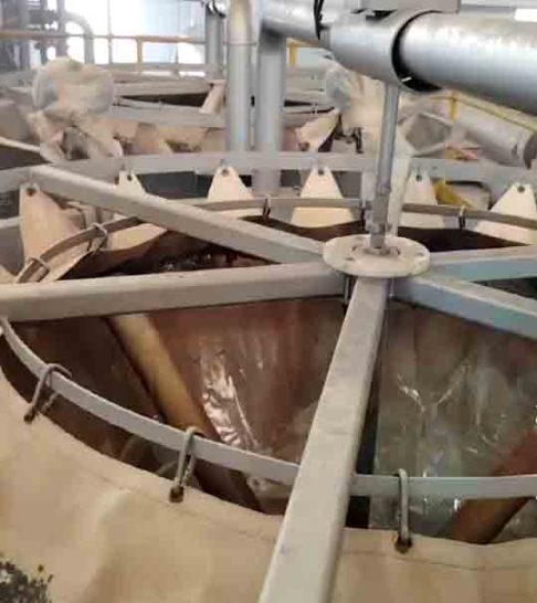
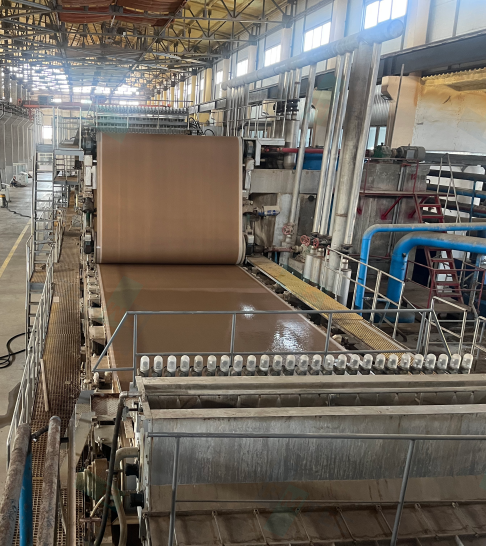
The size press divides the machine into three tension zones: before the press, through the nip, and after the press. Each zone has a distinct functional requirement, and the draw target in each zone reflects that requirement. The table below reflects long-term mill experience. These are reference ranges for a starting point — actual optimum values depend on grade, dryness, and machine speed as covered in Section 4.
| Section | Typical Draw (%) | Key Risk | Practical Role |
| Dryer Section → Size Press (Entry) | +0.5 ~ +1.5 % | Wrinkling / slack web | Builds light tension so the sheet lies flat against the applicator roll and receives a uniform coating film |
| Size Press → After-Dryer Section (Exit) | +1.0 ~ +2.0 % | Web sag / coating damage | Supports the moisture-weakened web immediately after coating; prevents sag, flutter and contact with equipment before starch film sets |
The exit draw is consistently set higher than entry draw across most machine types and grades. After passing through the nip and absorbing starch solution, the web is wetter and mechanically weaker than at entry. A higher exit draw is required to carry the web clear of the size press and into the after-dryer section without sag, flutter, or surface contact with equipment.
Diagnosing Draw-Related Problems
Most size press runnability problems can be traced to draw being outside the stable operating window. The three conditions and their characteristic symptoms are summarised below.
| Condition | Symptoms | Root Cause |
| Draw too high | Web breaks at splices or weak points; transverse shrinkage; edge cracking; curling at rewinder | Excessive tension stretches the sheet beyond its wet tensile limit, especially after size press where moisture has reduced strength |
| Draw too low | Slack sheet, flutter, wrinkling; uneven or missed coating; sheet contacts rolls or frame and smears wet starch | Insufficient tension allows the sheet to bag between support points; aerodynamic forces at high speed amplify instability |
| Draw inconsistent | Cyclic breaks; periodic coating defects (streaks, banding); tension spikes at splices | Roll diameter change, encoder drift, or rubber wear introduces hidden deviation between set and actual draw |
The third condition — draw inconsistency — is often the hardest to diagnose because it does not appear in steady-state settings. It manifests as cyclic or intermittent problems that resist correction because the root cause is a measurement or calibration error, not a settings error. If periodic defects persist despite correct-looking draw values, investigate encoder accuracy and roll diameter records before adjusting any set points.
Key Variables That Determine the Right Draw Setting
There is no single draw value that applies across grades and conditions. The appropriate setting is determined by the interaction of five variables. Understanding how each one shifts the safe operating window allows operators to anticipate adjustments rather than react after a problem has developed.
| Variable | Direction of Effect | Adjustment Guidance |
| Basis weight | Lower basis weight → lower wet strength → narrower safe window | Use more conservative draw for lightweight grades; do not transfer board-grade settings to tissue or specialty |
| Fibre furnish | High recycled or short-fibre content → reduced tensile strength and elongation | Reduce draw when recycled content increases; edge cracking is the first warning sign |
| Sheet dryness at size press entry | Lower dryness → weaker web → higher risk at any given draw value | Treat dryness and draw as a linked pair: when pre-press dryness drops, reduce draw proportionally |
| Machine speed | Higher speed amplifies aerodynamic forces; small draw deviations produce larger tension spikes | Above ~1,000 m/min, tighten the acceptable draw range and increase monitoring frequency |
| Starch solution properties | Higher solids or viscosity → heavier pickup → more moisture addition → greater post-press softening | After any starch formulation or concentration change, recheck exit draw before returning to full speed |
A practical rule of thumb: whenever two or more of these variables shift simultaneously — for example, a grade change coinciding with a dryness drop or a formulation change — treat the transition as high-risk and verify draw proactively before increasing speed.
Draw and Film Transfer Coating: The Connection That Is Often Missed
In film transfer size press systems, draw does not only affect web tension. It directly influences how the coating film splits and transfers onto the sheet surface.
The relative speed between the sheet and the applicator roll determines the shear force applied to the coating film at the point of separation. When draw is too high, shear force increases and disturbs the film before it has fully transferred, producing coating streaks, uneven distribution, or surface roughness. When draw is too low, incomplete film split results in coating dropout or patchy coverage.
The relative speed between the sheet and the applicator roll determines the shear force applied to the coating film at the point of separation. When draw is too high, shear force increases and disturbs the film before it has fully transferred, producing coating streaks, uneven distribution, or surface roughness. When draw is too low, incomplete film split results in coating dropout or patchy coverage.
This means that coating quality problems — including basis weight variation in the machine direction or cross-machine direction — can sometimes be traced to draw rather than to the starch formulation or metering system. When coating quality is inconsistent and the metering system has been ruled out, review draw stability and calibration accuracy before making chemistry adjustments.
A Structured Approach to Setting and Adjusting Draw
The following sequence applies when establishing draw settings for a new grade, returning from a major maintenance stop, or investigating a runnability problem.
Measure the actual working diameter of each driven roll, especially rubber-covered rolls that wear continuously. Enter corrected values into the drive control system. Confirm that speed encoders are returning clean signals — a drifting or intermittent encoder is one of the most common sources of unexplained draw instability and is frequently misdiagnosed as a settings problem.
Begin at the lower end of the reference range for both entry (+0.5%) and exit (+1.0%) draw. Bring the machine to operating speed and observe sheet behavior — entry flatness, contact stability at the applicator rolls, and open-draw behavior after the size press. Do not attempt to optimise at this stage.
Increase draw in steps of 0.1–0.2% and observe for at least 5–10 minutes at each step. Record the draw value and the corresponding sheet behavior. Once the sheet starts showing signs of overtension — edge tension, cross-direction tightness, or crease formation — reduce draw and record that boundary. The stable operating window lies between the too-loose boundary and the too-tight boundary.
Tension sensors at the size press entry and exit provide direct measurement of the parameter draw is intended to control. Where they are installed, calibrate draw settings to achieve a target tension range rather than relying solely on the draw percentage value. If tension measurement is not available, observable sheet behavior remains the most reliable real-time indicator.
Once a stable operating window is identified for a given grade and speed, record both the draw settings and the observable indicators that confirmed stability. This creates a repeatable reference that reduces re-establishment time after grade changes or stops and gives newer operators a reliable baseline to work from.
What Operators Should Watch
Control system values confirm what is set. Observable sheet behavior confirms what is actually happening. In practice, the sheet is the most reliable real-time indicator — use both, but trust what you can see.
Entry zone:
At the applicator rolls:
Exit open draw:
After-dryer entry:
The sheet should enter the size press smoothly with no visible loose folds, flutter, or lateral drift. Any lateral movement at entry often indicates draw imbalance between the entry drive and the applicator roll.
The sheet should maintain stable, consistent contact. Intermittent lift-off, bouncing, or edge separation are early indicators of draw instability — they signal a problem before the sheet condition deteriorates further.
The sheet should lift cleanly from the size press and travel without sag or flutter to the first after-dryer cylinder. Sagging in this zone is the most common indicator of insufficient exit draw.
The sheet should enter the first dryer cylinder without wrinkling or folding. Wrinkles appearing specifically at the first after-dryer contact point typically indicate excess moisture combined with insufficient or erratic draw.
One more note: if observable sheet behavior is stable but the control system reports a draw value outside the expected range, investigate calibration accuracy before adjusting the set point. In most such cases the discrepancy is in the measurement, not in the process.
Conclusion
Draw control around the size press is not a single number. It is a dynamic relationship between driven sections that must be actively managed in response to grade, dryness, machine speed, and equipment condition.
The most common source of draw-related problems is not incorrect settings but undetected deviation between set and actual draw, arising from roll diameter change, encoder error, or inadequate calibration practice. Measurement accuracy is therefore the foundation of stable draw control — everything else builds on it.
The practical sequence: verify measurement accuracy first, establish a conservative baseline, then optimise within the stable operating window — using observable sheet behavior as the primary feedback throughout.
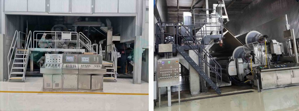
About PMTEC
PM Zhengzhou Technology Co., Ltd. (PMTEC) provides full-scope solutions for paper mills — covering paper machine systems, process engineering, and components. Draw control issues of the kind described in this article are commonly encountered during commissioning and system review work.
In most cases, improvements come from measurement calibration and structured adjustment methodology rather than hardware changes.