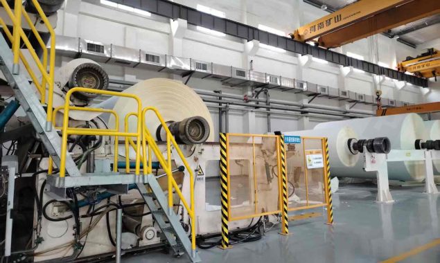
Foam in white water systems is a common problem in paper mills. The typical on-site response is to increase defoamer dosage — but this treats the symptom, not the cause. Foam tends to recur, and chemical costs continue to climb.
From a process engineering standpoint, the fundamental driver of white water foam is a continuous source of air within the system. Among the various air entry points, the design of makeup water piping into the off-machine white water tank is one of the most frequently overlooked — yet persistently impactful — contributors.
This article analyzes how makeup water piping design affects foam formation — covering inlet conditions, piping structure, and process parameter control — and offers practical field optimization and troubleshooting guidance for paper mill engineers.
Inlet Conditions: Where Air Entrainment Begins
How makeup water enters the white water tank is the first critical factor in determining whether air is introduced.
A common high-risk configuration positions the makeup water outlet above the liquid surface, creating a free-falling jet that impacts the pool. Because makeup water is relatively clean, this is often dismissed as harmless — but the jet impact entrains significant air, providing a persistent foam source.
The correct approach is to extend the makeup water outlet below the liquid surface, with low-energy flow directed along the tank’s natural flow path. This allows makeup water to merge smoothly into the system, eliminating surface-impact air entrainment at its source.
| Design Factor | Risk Condition | Recommended Design |
| Outlet position | Free-falling jet above surface | Submerged below surface |
| Flow mode | High-velocity impact, splashing | Low-velocity, smooth discharge |
| Flow direction | Perpendicular to surface | Aligned with tank flow direction |
Piping Structure: Hidden Air Sources Inside the System
Even with a correctly positioned inlet, poor hydraulic conditions within the piping itself can continuously introduce air. This is often the real reason foam recurs despite an apparently correct inlet.
Pipeline Sealing Integrity
Minor leaks at pipe joints, flange gaskets, or valve packing allow outside air to be drawn into any negative-pressure zone within the pipe. These leaks are not visually obvious and often only appear at higher flow velocities, making them easy to miss.
Pipe Diameter and Flow Velocity
Excessive velocity — generally recommended to remain within 1.0–1.5 m/s for white water piping — generates turbulence inside the pipe, promoting gas release and bubble formation. Velocity that is too low can allow gas pockets to accumulate and enter the system intermittently. Correctly sizing pipe diameter to maintain a stable velocity range is fundamental to preventing in-pipe air introduction.
Fittings and Bend Geometry
Abrupt bends, sudden diameter changes, or partially opened valves create local low-pressure zones that cause dissolved gases to come out of solution or draw in outside air. Pipe routing should minimize sharp bends, use long-radius elbows or gradual transition fittings, and follow the natural direction of flow.
Process Parameters: Often-Overlooked System Disturbances
Beyond physical design, poorly controlled makeup water process parameters can indirectly trigger or worsen foam.
Makeup Water Quality
If makeup water contains residual detergent, surfactants, or organic matter, these act as foam stabilizers, making bubbles harder to break and disperse. Makeup water sources and quality parameters should be monitored, and pre-treatment applied where necessary.
Sudden Changes in Temperature or pH
Abrupt changes in temperature or pH reduce gas solubility in white water, causing dissolved gases to come out of solution and increasing free bubble content. Makeup water temperature and pH should be maintained close to the existing white water system to avoid shock disturbances.
Flow Rate Stability
Fluctuating flow rates create periodic hydraulic shocks and pressure surges, causing cyclical release of dissolved gases. Flow control valves and stable control logic are recommended for important makeup water points to prevent intermittent high-flow impacts.
System-Level Design: Moving Beyond Localized Fixes
White water systems respond as a whole. Fixing a single point often fails to resolve the root cause and can sometimes generate new foam problems elsewhere in the circuit.
Several key system-level principles merit attention: collect and treat concentrated wire pit white water separately from dilution shower water, avoiding mixing air-rich dilute flows directly into the concentrated stream; route makeup water preferentially into high-volume buffer tanks or low-turbulence zones rather than directly into agitated chests or pump suction lines; and design the overall white water circuit on a smooth, low-turbulence basis, minimizing unnecessary cross-sectional changes and abrupt direction shifts.
At critical makeup water points or white water tank outlets, online air monitoring equipment or simple sight glasses can help with early detection and localization of air entrainment. For higher-risk makeup points, a small degassing box can be considered to allow entrained air to escape before water enters the main circuit.
Field Troubleshooting: Mechanical First, Chemical Second
When foam issues arise, mechanical and process design causes should be investigated first, before turning to chemical adjustment. The following five-step field inspection process helps rapidly identify makeup water piping problems:
- Observe: Check the makeup water inlet for visible splashing, siphon backflow, or vortexing — these are direct indicators of air entrainment.
- Listen: Stand close to the pipe — especially at joints and valves — and listen for irregular hissing or impact sounds, which typically indicate turbulence or air leakage into the pipe.
- Feel: Check pipe joints and valve bodies for fine vibration or air movement, which can indicate gas accumulation inside the pipe or active leakage points.
- Review: Examine the piping system’s modification history. A seemingly minor change — such as replacing a valve with a different specification or rerouting a section of pipe — can alter the hydraulic behavior of the entire system.
- Test: Temporarily reduce makeup flow rate or adjust the outlet position, and observe whether foam conditions immediately improve. If foam responds directly to mechanical changes, the root cause is process design rather than chemistry.
Conclusion
Foam is the symptom; air is the root cause. Through careful design of makeup water inlet positioning, piping structure, and process parameters, air entrainment can be systematically reduced at the source — lowering defoamer consumption and improving white water system stability.
This is not a matter of tuning an existing system — it is about correcting the process design itself. Many persistent foam problems in mill operations are not fundamentally complex; they have simply been masked by repeated chemical treatment and have not received adequate attention from a systems engineering perspective.
In PMTEC’s system reviews and engineering projects, air entrainment in white water piping is among the more frequently identified findings.
In most cases, targeted piping modifications or inlet condition adjustments — rather than equipment upgrades — deliver significant improvement in foam control.
If you have questions or would like to discuss a specific situation, the PMTEC technical team is happy to help.