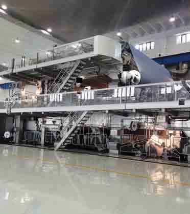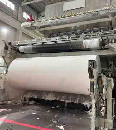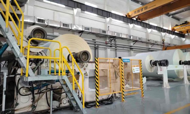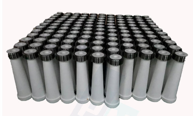

An air knife coater meters a pre-applied wet coating with a high-velocity air jet instead of a rigid blade. The jet follows the surface of the sheet rather than cutting to a fixed plane, which gives an even coat weight over an uneven base and explains why the method holds its place on paperboard, specialty grades and functional coatings. This article covers how the process works, what each subsystem has to deliver, typical design references and the information needed before a coating method is fixed.
Before the equipment question.
Target coat weight, base sheet, machine speed, available drying capacity and installation space decide the metering method, not the other way round.
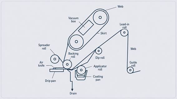
Figure 1. Air knife coating process and web path, from applicator to vacuum box and skirt.
How does an air knife coater work?
The base sheet first receives more coating than it needs, from an applicator roll or another application unit upstream. The web carries that excess around the backing roll and past a narrow slot jet, which blows the surplus back into a drip pan and leaves a controlled film behind. A vacuum box and skirt hold the sheet against the roll so that tension stays steady through the metering point.
Sequence at startup matters as much as the settings. The applicator is disengaged and the knife retracted during threading; only once web tension is stable does the knife move in and the application system engage. The distance between applicator and knife also decides how much water has already left the film at the metering point — too much dwell and the layer immobilises, too little and it has not fully wetted the sheet.
Why an air jet meters differently from a blade
A blade meters to a plane. It rides on the coating layer, fills the low areas of the sheet and leaves a levelled surface whose coat weight varies with the topography underneath. An air jet meters to a momentum balance, removing coating until the shear from the jet matches the resistance of the film left behind. The remaining layer follows the contour of the sheet at close to constant thickness. Four consequences follow:
Coat weight is even across the sheet, and optical coverage is even with it. Base sheet roughness is carried through rather than filled in, so smoothness has to come from the sheet and from calendering after the coater.
Nothing touches the wet film, so abrasive pigments wear no metering element and a weak or embossed web is not loaded mechanically.
Solids must stay low enough for the jet to move the coating, commonly 25 to 45 percent by weight against 60 percent and above for blade coating. More water per unit of coat weight means more evaporation, which makes drying capacity part of the coating method decision.
Metering stability and misting set a practical speed ceiling below blade or film transfer coating, dependent on formulation and grade.
Where does air knife coating perform well?
The strongest applications are coated paperboard, where an economical pre-coat is combined with an air-knife top coat, and specialty and functional grades where the coating carries a property rather than an appearance — barrier layers, adhesive and release coatings, and pigment systems with abrasive or shear-sensitive components. For very low coat weights at high speed, high gloss and smoothness targets, or high-solids formulations, blade, rod or film transfer coating usually gives a better result for the same investment.
| Metering method | Contact with wet film | Effect on the sheet | Where it fits |
| Air knife | None — air jet | Contour coat: even coat weight, base roughness carried through | Board top coats, specialty and functional grades, abrasive coatings |
| Blade | Yes | Levelled surface: coat weight follows base topography | High smoothness and gloss, high solids, high speed |
| Rod | Yes | Partly levelled, light and controlled coat weights | Pre-coats, light pigment and barrier layers |
| Film transfer | Film split, no metering at the sheet | Contour coat, both sides in one nip | Surface sizing, pigmented pre-coats, high-speed lines |
What are the main systems of an air knife coater?
Coating application system
The applicator must deliver a continuous, fully wetted layer before the sheet reaches the knife. The jet can only remove coating, never add it, so dry spots, skips and unstable flooding cannot be corrected downstream. Roll diameter, surface condition, nip geometry and speed ratio therefore set the limit on what the metering stage can achieve; multi-roll arrangements give more stable wetting at higher speeds.
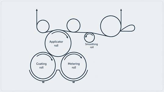
Figure 2. Three-roll coating application arrangement with smoothing roll.
Air supply and metering system
A typical package consists of a centrifugal blower, drive motor, air cooler and inlet and outlet filtration. Air volume follows from machine width, nozzle opening and operating pressure. The cooler and the filtration earn their place: air leaves a blower hot enough to change the coating at the lip, and one particle carried into the slot is one streak that runs the length of the reel. Because coat weight is governed by jet momentum, pressure and volume are set as a pair — and web speed, viscosity, solids and base sheet absorbency all shift the result, so the same nozzle setting will not give the same coat weight on a different grade.
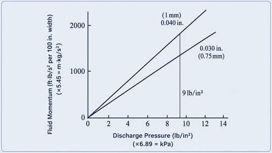
Figure 3. Jet momentum against discharge pressure for two nozzle openings.
Air knife geometry and cleaning access
An air knife has no segmented cross-direction actuators. The CD profile comes from the straightness of the lip, the uniformity of the opening across the width and equal air distribution from both ends of the plenum, which makes machining tolerance and lip condition after cleaning a matter of profile control rather than maintenance detail. Coating that dries at the nozzle creates streaks quickly and the streak does not clear itself, so rotary double-ended and clamshell constructions are used to bring a clean knife into service while the contaminated one is washed.
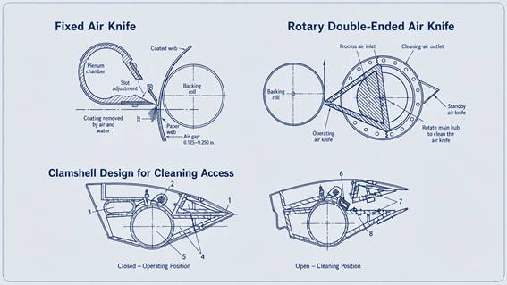
Figure 4. Fixed, rotary double-ended and clamshell air knife constructions, in operating and cleaning positions.
Backing roll and web run
The backing roll defines the metering geometry, and the gap is small enough that roll runout reaches the sheet directly as coat-weight variation. Cover hardness governs how far the web conforms under the jet, and cover condition after regrinding belongs in the maintenance plan. Wrap angle and lead-in geometry decide how much air the moving web drags into the metering zone; that boundary layer works against the jet and grows with speed.
Coating recovery and exhaust system
A recovery hood, baffle arrangement and exhaust system collect the mist the knife generates, limit contamination of the machine area and return usable coating where the formulation allows. Exhaust balance is a process setting rather than a fixed value: too much draw destabilises the web at the metering point, too little and mist reaches the dryer hood and the reel. Because the ducting runs under vacuum, coating dries on the internal walls, so wash-up access has to be designed in from the start.
What air pressure and nozzle settings are typical?
Preliminary references for conventional arrangements, not design limits. None should be applied without confirming the coating formulation, web speed, machine width and backing-roll geometry.
| Parameter | Typical reference | What moves it |
| Air pressure | Approximately 20.7 to 34.5 kPa in normal operation | Coat weight, viscosity, speed, acceptable misting and noise |
| Nozzle opening | Approximately 0.77 to 1.15 mm | Air volume available, coat-weight range, formulation |
| Nozzle to backing roll | Approximately 3 mm or slightly more | Web stability, sheet thickness, cleaning access |
| Air knife position | Around 12 mm below the backing-roll centreline | Drainage of removed coating, web path geometry |
| Installation angle | Slight downward inclination, around 1 degree | Removal of surplus coating away from the web |
Final settings are established through project-specific design and commissioning trials.
Where to look first when something goes wrong
| Symptom | First checks |
| Streaks in machine direction | Dried coating or damage at the nozzle lip; a particle in the slot; condition of the air filtration |
| CD profile off target | Uniformity of the lip opening; equal air supply from both ends; backing-roll runout and cover |
| Coat weight drifting in a run | Air temperature and cooler performance; solids and viscosity drift; applicator flooding stability |
| Skips and uncoated spots | The applicator, not the knife — coverage missing before the metering point cannot be recovered after it |
| Mottle or orange peel | Dwell time and immobilisation before metering; base sheet absorbency variation |
| Mist in the machine area | Exhaust balance and hood sealing; pressure set higher than the coat-weight target requires |
| Drying load above expectation | Coating solids too low for the target coat weight; check the formulation before adding dryer capacity |
What information is needed to specify or upgrade a coating section?
The technical route should follow from actual production conditions rather than from equipment type. For a first review:
Grade and furnish
|
base sheet structure, absorbency, surface condition and the property the coating has to deliver.
Production targets
|
machine width, operating speed, target coat weight per side and the quality improvement expected.
Coating properties
|
solids, viscosity and rheology, temperature, abrasiveness and foaming tendency.
Drying capacity
|
sheet dryness entering the coater, available dryer length and maximum evaporation load.
Mechanical integration
|
existing general arrangement, floor space, web path, threading access and maintenance clearances.
Utilities and controls
|
electrical load, blower and compressed air, exhaust, wash water, coating preparation and automation scope.
On a rebuild, the general arrangement and current operating conditions usually reveal the real constraint before any equipment is discussed. Drying capacity and installation space rule out more coating concepts than performance ever does.
About PMTEC
PMTEC is a full mill solutions provider for the pulp and paper industry, working as a process-aware integrator across stock preparation, paper machine systems, coating and converting, and mill operations. The considerations above reflect how coating-section projects are approached in practice, where the metering method follows from the base sheet, the coating and the available drying capacity.